
Views: 0 Author: Site Editor Publish Time: 2026-08-04 Origin: Site


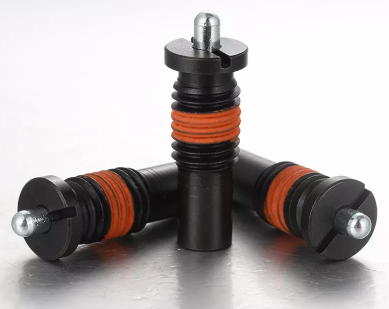
Precise component positioning in mechanical assemblies dictates the difference between seamless indexing and mechanical binding. A fraction of a millimeter in plunger travel matters. Engineers must control this movement to ensure reliable machine operation. Incorrect travel specification carries severe engineering consequences. Insufficient stroke leads to missed detents or causes the internal mechanism to bottom out. Excessive stroke introduces side-load vulnerabilities and creates spatial conflicts within compact machine footprints. You cannot rely on basic thread size alone to specify these components. Engineers require a rigorous evaluation framework for spring plunger travel selection. You must analyze engagement depth, nose length, and spring force curves against application-specific constraints. Proper selection prevents premature wear and mechanical failure. We will break down the exact mechanical differences between travel options so you can match plunger stroke to your specific indexing, fixing, or ejection requirements.
Travel vs. Tolerance: Long stroke spring plungers provide a wider operational window for a nose to catch a detent without forcing the internal spring to bottom out, making them highly forgiving in assemblies with variable machining tolerances.
Space Constraints: Short stroke spring plungers are mandatory for low-profile applications but require highly precise mating components to prevent engagement failure.
Force Dynamics: Spring force is not static; longer strokes experience a more gradual force curve, whereas short strokes ramp up rapidly, impacting the tactile feel and mechanical resistance during actuation.
Application Matching: Ejection, stop functions, and deep workpiece fixing inherently require long-stroke models, while high-frequency, shallow indexing favors short-stroke designs.
The device relies on a precise interplay between three main components: a threaded housing, an internal compression spring, and a cylindrical nose. The housing length scales to accommodate different stroke requirements. A longer stroke requires a longer internal cavity to house the uncompressed spring without coil binding. The threaded body secures the unit into the mating fixture, typically utilizing standard metric or imperial threads. The nose pin extends outward to engage the workpiece. Manufacturers calibrate the internal spring to deliver specific initial and final loads, often using music wire or stainless steel depending on the required fatigue life. The entire assembly works as a single cohesive unit to provide repeatable positioning across thousands of cycles. You must match the housing material—whether black oxide steel, stainless, or brass—to the environmental conditions of your shop floor.
Successful plunger actuation requires repeatable engagement and zero binding. You need optimal retention force without permanent deformation of the pin or the workpiece. The nose must enter and exit the detent smoothly. It should not catch, gall, or drag on the mating surface during lateral transitions. The internal spring must compress fully without reaching its solid height. The threaded housing must remain secure under continuous machine vibration. You measure success by the lifespan of the component and the consistency of the indexing action. A properly specified plunger operates for millions of cycles. It maintains consistent force and positional accuracy throughout its service life, requiring minimal maintenance or adjustment after the initial installation.
Total stroke represents the maximum physical travel of the nose from its fully extended position to its fully retracted position flush with the housing. Functional engagement depth is the portion of the stroke actively used in the application. These two metrics are rarely identical. You must design the mechanical system so functional engagement is always less than total stroke. The exposed nose length directly relates to the internal spring cavity geometry. A longer exposed nose requires deeper internal clearance. The pin must retract fully into the housing during operation to clear the workpiece. Understanding this geometric relationship prevents spatial conflicts. It ensures the pin clears the workpiece during lateral transitions, preventing shear forces from snapping the nose.
Mechanical failure occurs when a plunger compresses beyond its maximum stroke. We call this bottoming out. The internal spring coils compress until they physically touch, reaching their solid height. At this point, the spring can no longer absorb kinetic energy. The remaining force transfers directly through the solid spring mass into the threaded housing. This places extreme stress on the internal components and the mounting threads. It can cause the housing to fracture or strip the threads in softer aluminum fixtures. Bottoming out also transfers unintended shock loads back into the mating components, potentially damaging delicate workpieces. It destroys the tactile feel of the indexing mechanism, replacing a smooth engagement with a harsh mechanical stop. You prevent this by calculating the exact travel distance and integrating hard stops into the fixture design.
Engineers utilize long stroke spring plungers for their extended cylindrical nose design. They feature a proportionally larger internal spring housing to accommodate the longer wire length. The extended travel creates a wider margin for error in detent alignment. This ensures positive locking despite shifting tolerances in welded assemblies or heavy castings. The longer internal spring provides a smoother force curve. The resistance increases gradually as the nose retracts, following a lower spring rate. This gradual compression reduces operator fatigue during manual indexing tasks. It also minimizes shock loads in automated pneumatic systems. The extended pin offers deeper penetration into mating holes. This deep engagement provides superior holding power for heavy workpieces that generate significant lateral forces during machining operations.
Ejection and Part Removal: The extended travel physically pushes parts out of injection molds. It clears heavy components from progressive stamping dies and automated welding fixtures.
Positive Stop Functions and Workpiece Fixing: The extended cylindrical nose acts as a rigid travel limit. It securely holds large castings during high-vibration CNC milling operations.
Variable Tolerance Assemblies: These accommodate shifting gaps in sheet metal fabrication. They absorb dimensional variations in heavy machinery frameworks where precision alignment is impossible.
Deep Detent Indexing: They secure heavy rotary tables and trunnions where shallow pins would shear under massive rotational torque.
Safety Interlocks: The long visual extension provides clear confirmation that a machine guard or locking mechanism is fully engaged.
These components require deeper tapped holes. They demand thicker housing materials on the mounting fixture to support the extended threaded body. You cannot install them in thin-walled enclosures or compact electronics. The long nose becomes vulnerable to lateral loads when fully extended. Side forces act on the pin like a lever, multiplying the stress at the base. This bending creates internal friction. It causes the pin to bind inside the housing, preventing smooth retraction. You must account for this shear stress during the design phase by ensuring loads remain perpendicular to the pin axis. The longer threaded body also increases installation time. It requires more clearance behind the mounting plate, which can interfere with moving machine parts or internal wiring routes.
Engineers specify short stroke spring plungers to achieve a compact footprint. They offer minimal nose protrusion and utilize specific internal components that allow for space-saving integration. The compressed internal geometry causes rapid spring force engagement. The force spikes quickly over a short distance due to a high spring rate. This provides crisp, immediate tactile feedback for the operator. The stubby nose resists lateral shear forces much better than extended pins. The short housing fits easily into confined spaces. It threads directly into thin metal plates, shallow blind holes, and low-profile extrusion profiles without protruding out the back side.
Tight Enclosures: They integrate seamlessly into thin-walled components. They fit low-profile assembly jigs and compact consumer electronics where internal space is at a premium.
High-Frequency Indexing: They excel in applications requiring rapid, shallow clicks. You find them in rotary dials, gear selectors, and optical adjustment stages.
Lightweight Fixturing: They hold small, delicate parts like circuit boards or plastic housings without applying excessive lateral pressure that could cause warping.
Space-Restricted Automation: They provide positioning feedback in robotic end-effectors and grippers with minimal payload impact and zero spatial interference.
Short travel demands strict machining tolerances on mating detents. A slight misalignment causes the pin to miss the hole entirely, resulting in a complete loss of holding force. You must prevent bottoming out through precise depth-stop integration. Accurate thread positioning is mandatory. You must calculate the exact distance between the plunger face and the workpiece using a depth micrometer. Use fine-threaded housings to achieve micro-adjustments during the initial installation. Implement rigid guide rails or linear bearings to prevent lateral shifting of the workpiece. This ensures the shallow pin aligns perfectly with the receiving detent on every single cycle. Regular CMM verification of the mating parts ensures the tolerances remain within the acceptable window for short-stroke engagement.
Engineers must first clarify the baseline choice before selecting stroke length. You select cylindrical nose plungers for positive locking, fixing, and ejection. Both long and short stroke nose designs provide a flat bearing surface on the side of the pin. This surface prevents the workpiece from sliding laterally once engaged. Ball plungers operate differently. They are reserved for smooth, rolling lateral transitions. They handle heavy load bearing during sliding movements across flat plates. A ball plunger cannot provide the deep, rigid locking of a long cylindrical nose. It also lacks the distinct tactile snap of a short stroke nose plunger. If your application requires the workpiece to lock firmly in place and resist side loads, you must use a nose plunger and then determine the appropriate stroke length.
You must calculate the maximum allowable housing length for your specific fixture. Compare this against the minimum required engagement depth to hold the part securely. A thick mounting plate allows for long stroke designs, giving you maximum flexibility. A thin plate restricts you to short stroke models. Consider the clearance behind the mounting plate. The threaded body cannot protrude into moving machine parts, hydraulic lines, or electrical harnesses. Measure the physical gap between the plunger face and the workpiece. The stroke must bridge this gap and still provide sufficient detent engagement. Use 3D CAD models to simulate the full range of motion, ensuring the pin clears the workpiece during tool changes or part indexing.
Long cylindrical noses have vastly different shear stress limits than short, stubby noses. A fully extended long pin acts like a lever arm. Lateral forces multiply at the base of the pin where it exits the housing. This impacts the internal sliding friction between the pin and the housing bore. It can cause the plunger mechanism to bind over long stroke lengths, preventing the internal spring from pushing the pin back out. Short stroke pins resist bending naturally. Their short length minimizes leverage. They handle lateral impacts more effectively without galling the internal bore. You must align the side load perpendicular to the pin axis. Angular loads increase the risk of binding in both designs, but long strokes will fail much faster under angular stress.
Hooke's Law dictates spring behavior. The formula F = kx explains how initial and final forces differ based on the spring constant (k) and the displacement (x). A long internal spring has a lower spring constant. The force increases gradually as the pin retracts. A short internal spring has a high spring constant. The force spikes quickly over a very short distance. These force curves directly impact operator ergonomics. Manual indexing benefits from the smooth, predictable curve of a long stroke. Automated indexing often requires the rapid force ramp-up of a short stroke to ensure immediate engagement. You must match the force profile to the actuation method to prevent operator fatigue or mechanical stalling.
Engineering Metric | Long Stroke Spring Plungers | Short Stroke Spring Plungers |
|---|---|---|
Functional Engagement Depth | Deep penetration; ideal for heavy workpiece retention and ejection. | Shallow penetration; optimized for rapid, high-frequency indexing. |
Tolerance Forgiveness | High; absorbs dimensional variations in welded or cast assemblies. | Low; requires precise CNC machining for mating detents. |
Installation Space Required | Requires deep tapped holes and thick mounting plates. | Fits thin walls, tight enclosures, and shallow blind holes. |
Spring Force Curve (Hooke's Law) | Gradual increase (low spring rate); smooth manual operation. | Rapid spike (high spring rate); crisp tactile feedback. |
Side Load Vulnerability | Higher risk of bending, galling, and internal binding. | Lower risk; stubby pin resists shear forces effectively. |
You must specify the correct geometry for mating holes on the workpiece. The chosen stroke and nose shape dictate this geometry entirely. Long stroke pins require deep, straight bores or steep V-grooves machined with a chamfer mill. The angle of the V-groove determines the retraction force required to disengage the pin. A 90-degree groove requires significantly more lateral force to disengage than a 120-degree groove. Short stroke pins work well with shallow spherical dimples created by a standard drill bit or ball end mill. Ensure the detent diameter slightly exceeds the pin diameter by at least 0.1mm. This prevents the pin from wedging into the hole and binding. Chamfer the edges of the detent to facilitate smooth pin entry and exit during rapid indexing.
Particulate ingress ruins plunger functionality faster than mechanical wear. Coolant, metal chips, or grinding dust can jam the extended travel path. Long-stroke models expose more pin surface area to the environment. Debris clings to the extended pin and retracts directly into the housing. This causes internal binding and destroys the spring. Harsh environments require sealed plungers with internal O-rings. You may need specific material finishes based on the application. Stainless steel housings resist corrosion in wet machining environments. Delrin or nylon noses prevent marring on soft aluminum or plastic workpieces. Evaluate the operating environment, including temperature extremes and chemical exposure, before specifying the travel length and material.
Thread-locking prevents back-out under high-cycle vibration. Apply a medium-strength liquid thread locker during installation, or use plungers with pre-applied nylon locking patches. You must establish strict inspection intervals for spring fatigue. Monitor the nose for abrasive wear based on stroke utilization and cycle counts. High-speed automated systems require frequent inspections, often weekly. Manual indexing fixtures require less maintenance but still need periodic checks. Replace the plunger immediately if the pin fails to extend fully or if the retraction feels gritty. Do not attempt to lubricate sealed plungers with heavy grease, as this attracts dust, packs the internal cavity, and accelerates wear.
Measure the available installation depth within your mounting fixture using a depth micrometer to establish your maximum allowable housing length.
Calculate the required engagement distance based on the lateral forces your workpiece will generate during operation.
Prototype the assembly with both travel lengths if your mating part tolerances exceed standard machining variations.
Apply a medium-strength anaerobic thread locker to the plunger body during final installation to prevent back-out from high-frequency vibration.
A: The primary difference lies in the length of the nose travel and the required installation depth. Long stroke models offer deep engagement and high tolerance forgiveness but need more space. Short stroke models fit tight spaces and provide shallow indexing but require precise detent alignment.
A: You determine this by calculating mating part tolerances, required holding force, and available physical space. Measure the gap between components. Ensure the chosen stroke provides sufficient detent engagement without forcing the internal spring to bottom out at maximum compression.
A: While they offer deep engagement, fully extended long noses are highly susceptible to shear stress. Heavy lateral forces can bend the pin and cause internal binding. Short stroke models or ball plungers handle side loads much more effectively.
A: Bottoming out crushes the internal spring coils together. This destroys the indexing function and transfers extreme kinetic shock to the threaded housing. It leads to housing fracture, spring failure, and mechanical damage to the mating workpiece.
A: Use a short stroke nose plunger for positive locking and rigid stop functions where you need a distinct cylindrical engagement. Use ball plungers for smooth, rolling lateral transitions and applications involving heavy sliding loads.
A: Yes. Longer strokes require deeper, more precisely angled receiving holes or V-grooves. This utilizes the full travel without causing the extended nose to bind upon retraction. Short strokes typically use shallow dimples or slight depressions.


